Brillouin-Mandelstam light scattering fundamentals
Brillouin-Mandelstam light spectroscopy (BMS), similar to Raman light spectroscopy, is the inelastic light scattering of monochromatic laser light by phonons. While in Raman light scattering technique, it is possible to observe phonons with minimum energies of 250 GHz or higher at the Brillouin zone center, BMS can probe phonons with very low energies in the range of 2-900 GHz. Therefore, with recent technological improvements in our Raman and Brillouin-Mandelstam light scattering systems, we are able to observe phonons with few gigahertz up to several terahertz energies close to the zone center. Both light scattering from the bulk, i.e. the volume of the sample, via the elasto-optic mechanism and from the surface of the sample, via the surface ripple mechanism can be detected with the BMS instrument.
Scattering from bulk phonons
Suppose that an acoustic phonon (sound wave) with the wave-vector of q and frequency of ω is travelling inside the medium. Acoustic phonons propagating through a medium induce local modulations in dielectric constant ε of material from which light can be scattered1. Assume an incident light with the wave-length of λo and wave-vector ki (|ki|=2π/λo) enters into a material with the refractive index of n (Figure X2). In this case, the wave-length and wave-vector of the incident light will change to λo/n and k*i (|k*i|=2πn/λo), respectively. The frequency of the light will not change when entering from one medium into another. The light with the wave-vector of k*i and ωi is scattered into the state of k*s and ωs by the bulk (volumetric) phonons according to the following equations 1:
(1) k*s - k*i = +/- q
(2) ωs - ωi = +/- ω
These equations are the conservation of momentum and energy equations, respectively. In these equations, the “plus” and “minus” signs refer to anti-stokes (absorption or annihilation) and stokes (emission) of the phonon.
Photons (incident and scattered light) have a linear dispersion and thus, the frequency of the incident and scattered light can be expressed in terms of light speed in vacuum c and the refractive index of medium n as follow:
(3) ωs = (c/n)|ks|
(4) ωi = (c/n)|ki|
.jpg)
Figure (a)
.jpg)
Figure (b)
Figure X2| Schematic of light scattering from bulk phonons. (a) General schematic of light scattering from bulk phonons. The incident and scattered light is demonstrated using arrows with green and blue colors. The purple arrow shows the acoustic phonon wave-vector. Here, ϕ is the scattering angle (angle between the incident and scattered light inside the material) which is different from the incident light angle (θi) (b) Schematic of the light scattering from bulk phonons in backscattering configuration. Here, the scattering angle ϕ is 180ᵒ. The backscattering configuration gives the maximum (largest) phonon wave-vector which can be probed by BMS technique.
The laser light typically used in Brillouin-Mandelstam scattering has a wave-vector in the order of ~105 cm-1 which only covers a very small portion of Brillouin zone (~108 cm-1)[2]. Therefore, according to equation 1, the acoustic phonons with wave-vector very close to the Brillouin zone center can be probed using this technique. The acoustic phonons in the vicinity of the Brillouin zone center has a linear dispersion as follow:
(5) ω = v|q|
in which υ is the sound velocity in the material. Thus, with respect to equations (3) to (5), equation (2) can be rewritten as follow:
(6)(|ks|-|ki|)/n|q| = v/c
The order of magnitude of υ/c is ~10-5 and hence, we can assume that |ks| ≈ |ki| = k in which k = 2πn/λ and λ is the excitation laser wave-length in vacuum. Considering this and according to equation (1), the phonon wave-vector would be:
(7)|q| = (4πn/λ)sin(ϕ/2)
In this equation, ϕ is the scattering angle and has been shown in Figure X2(a). In the backscattering configuration (Figure X2(b)), the scattering angle ϕ is 180ᵒ and therefore, the phonon wave-vector in backscattering configuration is:
(8)|q| = (4πn/λ)
As one can see, in backscattering geometry, phonon wave-vector is only dependent on the refractive index of scattering medium (n) and the excitation wave-length of probing laser (λ).
Scattering from ripple mechanism
In opaque materials and thin films, the ripples produced by the excitation laser on the surface of the sample can scatter light. High optical absorption limits the scattering volume to the surface of the material which can affect the wave-vector conservation law. Indeed, in many cases, as materials with high absorption coefficient and thin films, ripple scattering would be the dominant scattering source. In this case, the phonon wave-vector is conserved in the direction parallel to the surface of the sample (Figure X3). Therefore, for the momentum conservation we can write3:
(9)|q||| = |ki|sinθi + |ks|sinθs
in which q|| is the phonon wave vector parallel to the surface and θi and θs, are the angle of incident and scattered light with respect to the normal to the surface, respectively. In the backscattering geometry, θi = θs = θ and thus, the phonon wave vector will be:
(10)|q||| = (4πn/λ)sin(θ)
As one can see from equation (10), the phonon wave vector depends on laser incident angle θ and its wavelength which means that with changing the laser incident angle, one can change phonon’s wave vector.
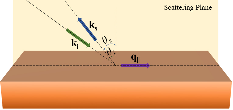
Figure X3
Figure X3| Schematic of the light scattering from ripple mechanism in backscattering configuration. Here, ki and ks are the incident and scattered light wave-vectors. The phonon wave-vector, q||, is parallel to the surface of the sample at the intersection of the “scattering plane” and sample’s surface. Unlike scattering from bulk phonons, the wave-vector of the surface phonons, q||, is dependent on the incident and scattered light angles denoted by θi and θs, respectively. Usually, in the backscattering geometry, θi = θs and therefore, q|| can be varied solely by changing the incident light angle.